|
2001 DEC /12
a decoder-encoder
combined IC has special function for co-frequency communication,
it can be the baseband of transceiver in various remote system,
such like infra-ray, wire or wireless control.
The decoder or
encoder has four addresses to configure, the decoder can
distinguish the right code from four encoders with four
different address transmitting simultaneously. each encoder has
eight digital switches to remote, but they are designed for four
of three switches, it’s useful to apply this IC to the remotes
that work at the same radio frequency without interfering one
another.
此編解碼IC可用於任何無線或有線收發器之基頻調變和解調變上,IC有4個address可供選擇,此IC特殊性在能分辨正確控制信號而不互相干擾,既使4組發射器使用同一頻率同時發射.
if you have any
question about this IC, please contact
us.
(lily.cn@msa.hinet.net)
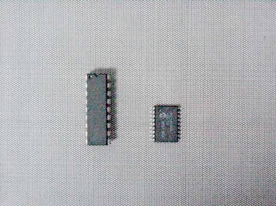
IC pin configuration
(top view) :
 18
17
16
15
14
13
12
11
10
18
17
16
15
14
13
12
11
10

1
2
3
4
5
6
7
8
9
1. address bit 0
2. address bit 1 3. NC
4. VCC 5.
GND 6. switch bit 0
7. switch bit 1
8 switch bit 2 9. switch bit 3
10. switch bit 4
11. switch bit 5 12. switch bit 6
13. switch bit 7
14. VCC 15. NC
16. RC timing circuit
input
(connect a series
R=3.9K to VCC and a shut C=220P to GND external)
17. VCCà
select to be a decoder ,or GND
à
select to be an encoder
18. code input when
decoder ,or code output when encoder (TTL level)
note1: switch bit
0-7 are inputs when encoder, or outputs when decoder.
They are all
for TTL level.
(impedance >
10K when input, current <10mA when output).
note2: VCC=+2.5 to
8 V
note3: 4 of 3
switches : SW2-SW0-SW3 , SW2-SW1-SW3
SW6-SW4-SW7 , SW6-SW5-SW7
where SW2-SW0-SW3
=>SW0 or SW2 or SW3 or SW0+SW2 or SW0+SW3
SW2-SW1-SW3
=>SW1 or SW2 or SW3 or SW1+SW2 or SW1+SW3
SW6-SW4-SW7
=>SW4 or SW6 or SW7 or SW4+SW6 or SW4+SW7
SW6-SW5-SW7
=>SW5 or SW6 or SW7 or SW5+SW6 or SW5+SW7
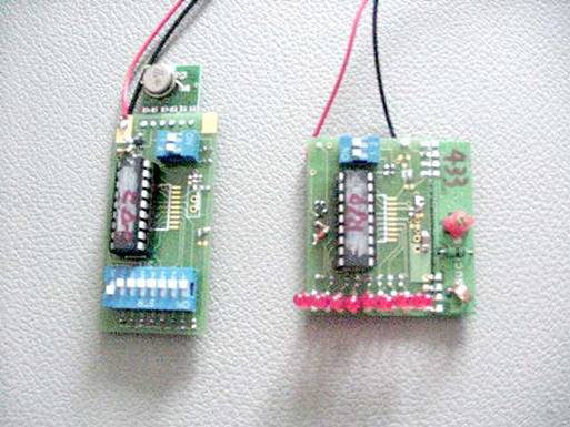
Fig1. This picture shows
the ICs applying in a pair of wireless control
|


